November 21, 2022 - by Santina Russo
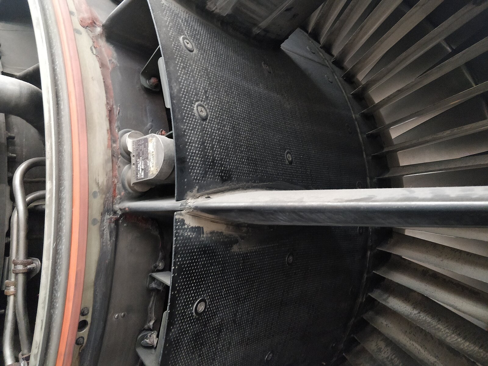
As everyone who has ever flown in an airplane will remember, the roar of an aircraft engine can be rather loud, especially during take-off and landing. The powerful engines required to bring multi-ton planes up in the air would, however, sound even louder, were it not for the acoustic liners. These metal elements coat the engines’ inner walls and swallow the better part of the noise.
To achieve this, the acoustic liners comprise a pattern of cavities with orifices that are one to two millimetres in diameter, which reduce the noise from the engines by acting as so-called Helmholtz resonators. An everyday example of such a resonator is a glass bottle that, when blown upon, produces a whistling sound. This happens because the cavity of the bottle is amplifying just one acoustic frequency. A similar principle applies to the much smaller cavities of an acoustic liner: Through their size and structure, they are tuned to absorb the main noise frequency generated by the movements of the engine blades.
Neglected aerodynamics
While these acoustic liners are clearly favourable for noise management, their effect on aerodynamic properties was long overlooked and understudied. The acoustic liner’s cavities make for a rough surface, so it was expected that they would increase aerodynamic drag. “Specifically, how much aerodynamic drag they cause has never really been understood before,” says Davide Modesti, an assistant professor of aerospace engineering at Delft University of Technology, Netherlands. Modesti and his co-workers performed fluid mechanics simulations recently on CSCS’s supercomputer “Piz Daint” to finally find out: How substantial is the added aerodynamic drag, and on what geometrical properties does this depend? And looking into the future: Should the design of today's acoustic liners be improved, and if yes, how do we achieve favourable effects on both noise and aerodynamics?
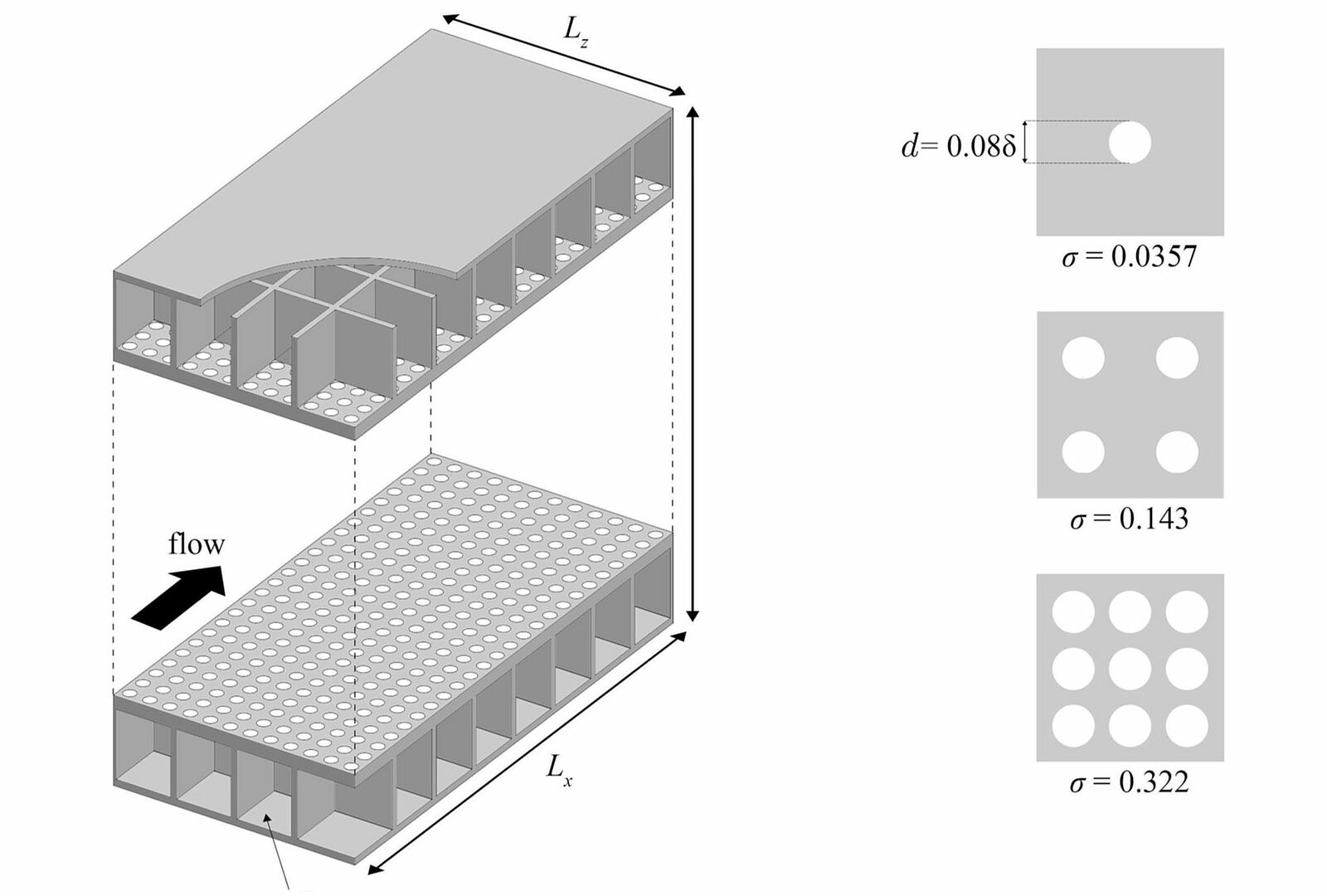
To begin to answer these questions with their numerical simulations, Modesti and his co-workers studied the so-called boundary layer. In these few centimetres near a body’s surface, the airflow is rather chaotic and characterised by a variety of vortices and turbulent flow structures with different time and length scales, even along smooth surfaces without any irregularities or perforations.
GPU-accelerated simulations
To find out how the flow is affected by the regular pattern of holes of acoustic liners, Modesti and his team ran a set of numerical fluid dynamics simulations on “Piz Daint” using the STREAmS solver software, which is optimised for the usage of graphic processing units (GPUs). In different runs, the team varied multiple parameters in the acoustic liners’ geometry — for instance, the diameter of the cavities, their number per sample area, and the thickness of the top plate — and then tested the resulting effect on aerodynamic drag compared to a smooth surface.
The results showed that aerodynamic drag cannot be looked at in connection with the cavities’ diameter alone. “This is easy to understand if you imagine that you can keep the diameter fixed but still alter the surface greatly by increasing the number of orifices,” illustrates Modesti. So, it is the combination of cavity diameter and cavity number that must be taken into account, the so-called porosity, which is the ratio of the area of the cavities to the total area of the acoustic liner.
“We have to think of acoustic liners as porous surfaces,” deduces Modesti. As the simulations further clarified, the added aerodynamic drag depends on a related property — namely permeability, meaning the ease with which a flow will pass through a porous surface. The results showed: The higher the permeability of the acoustic liners’ surface, meaning the more the flow enters the cavities and interacts with them, the higher the added aerodynamic drag. Dominant is especially the non-linear part of the permeability, which can be calculated for each acoustic liner geometry with comparatively slim simulations that can be run on laptops.
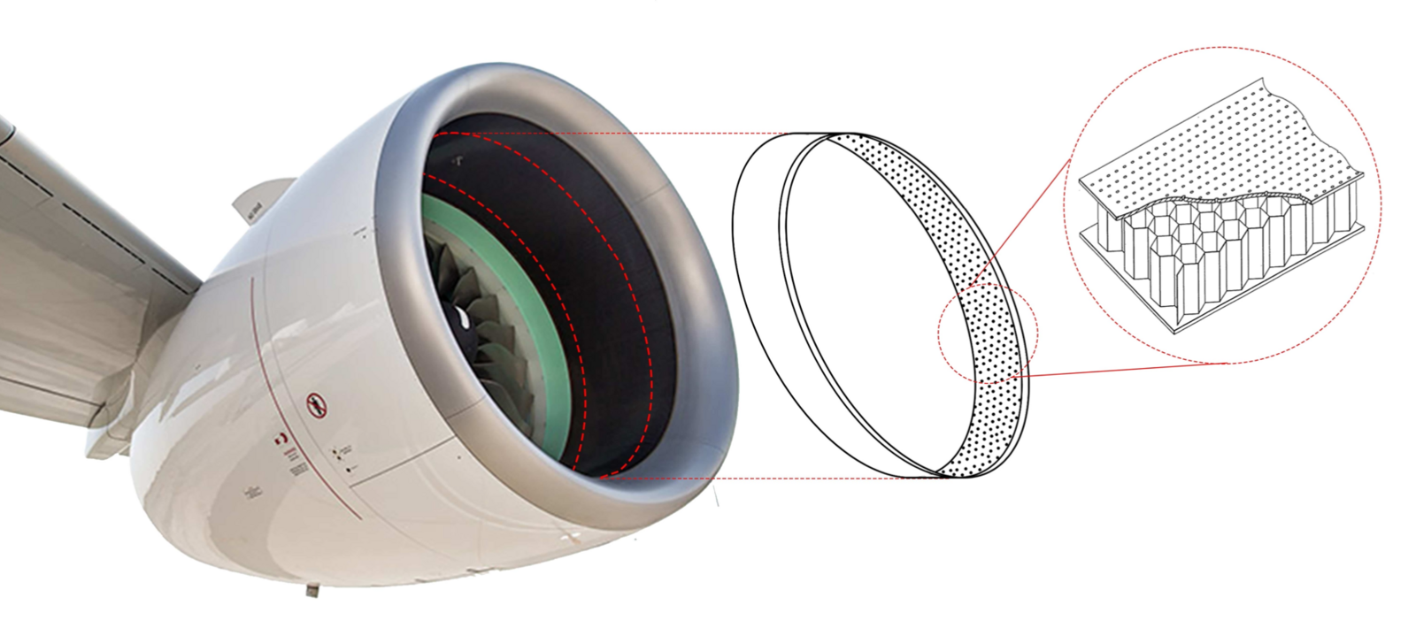
In addition, to a lesser degree, aerodynamic drag is also affected by the thickness of the acoustic liner’s perforated top plate, as Modesti and his co-workers found: The thinner the plate the higher the added drag. Typically, the plate’s thickness corresponds to the diameter of the cavities, so one to two millimetres; but depending on the geometry of the perforations, this could be optimised.
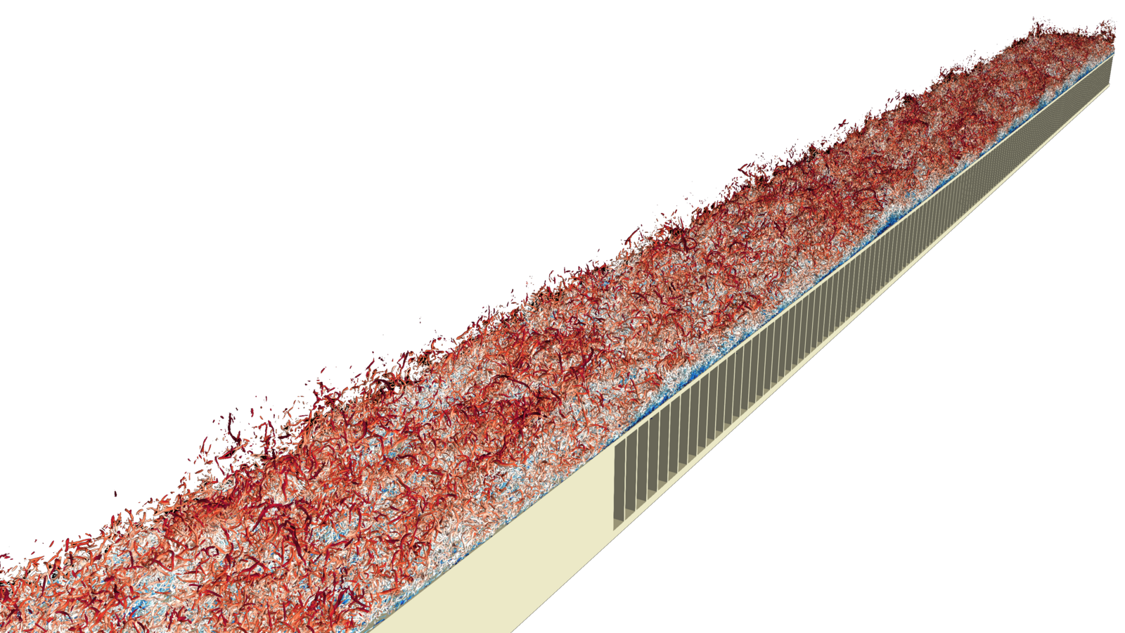
The video illustration from Modesti’s simulations shows the acoustic liners with the airflow at the boundary layer close to their surface. The colours refer to flow velocity: blue is low, and red is high velocity. The calculations were performed at Mach number 0,3, which is typical for take-off and landing and means that the aircraft is moving at 30 percent of the speed of sound. The full video was entered into the gallery of fluid motion contest at the 75th Annual Meeting of the APD Division of Fluid Dynamics. Find the full video also on Youtube. (Video: Jean M. Favre, CSCS)
Today’s acoustic liners: a sound choice?
Previous studies investigating acoustic liners had left a lot of uncertainty. For example, they found very different values of added drag, from 15 to over 500 per cent depending on various geometries. “This variability in the results made it all but impossible to deduce a comprehensive relationship,” says Modesti. Only by recognizing that acoustic liners can and should be regarded as porous surfaces were he and his team able to build a mathematical theory that both consistently describes the liners’ effect and also predicts the added drag from a given perforation geometry.
By applying the newly found mathematics to common acoustic liners used today, the team found that the components cause a 70 percent drag increase per plane area compared to a smooth surface. Extrapolated to the entire surface of common aircraft, this amounts to a drag increase of one to two percent — slightly dependent on the aircraft model — from the acoustic liners alone. “This also means that acoustic liners are responsible for around two percent of fuel consumption,” says Modesti. This may not sound overly dramatic, but in fact, it is: “When you start multiplying this amount with entire aircraft fleets and with the frequency of flights, numbers soon start to soar,” explains Modesti. “We are talking of billions of dollars for the aviation industry.” That’s why aircraft operators and manufacturers are interested in every little decrease of aerodynamic drag.
How to smooth things out
All of this means that today’s acoustic liners could indeed be improved. “To reduce drag from acoustic liners, aircraft manufacturers should minimize the components’ permeability,” concludes Modesti. To achieve this, a particular coefficient related to permeability should be maximized, the so-called Forchheimer coefficient, which can be calculated from an acoustic liner’s perforation geometry and top plate thickness. “The challenge will be to maximize this coefficient while at the same time retain the liners’ noise-reducing capabilities,” says Modesti.
The scientist and his team are currently working on a project to help with precisely that. For this, they have enhanced their simulation setup to include acoustic waves. “The aim there is to relate the permeability of the acoustic liners to their noise reduction properties,” says Modesti, and to ideally find a way to jointly optimise both noise reduction and aerodynamic drag.
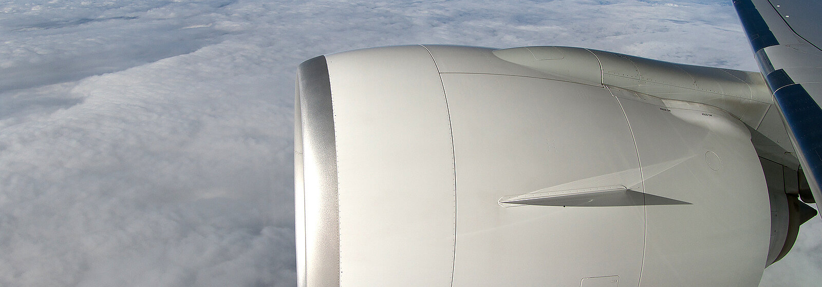
Image on top: One of the engines of a Swiss Airlines Boeing 777. (Image: Wikimedia commons, Bernd K)
References:
- Shahzad H., Hickel S. and Modesti D.: Permeability and Turbulence Over Perforated Plates. Flow Turbulence Combust (2022). DOI: https://doi.org/10.1007/s10494-022-00337-7
- Shahzad H., Hickel S. and Modesti D.: Turbulence and added drag over acoustic liners. Submitted. Preprint: https://arxiv.org/abs/2210.17354
This article may be used on other media and online portals provided the copyright conditions are observed.